

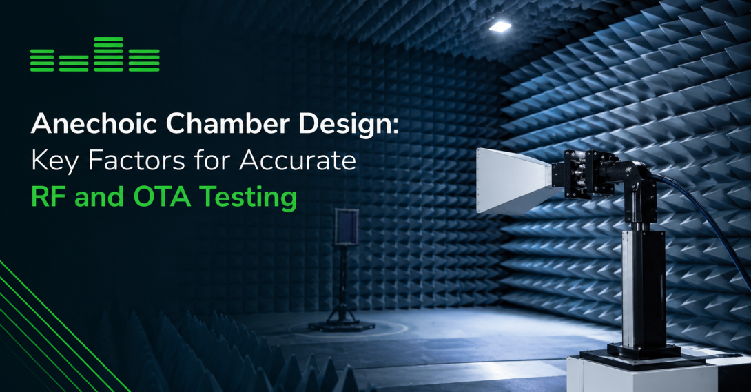
An accurate wireless measurement depends on more than the device under test. The surrounding environment also plays an important role. Reflected radio frequency (RF) signals, external interference, and inconsistent test setups can affect measurement results, making it difficult to distinguish actual device performance from environmental influences.
This is where anechoic chamber design becomes important. A well-planned chamber creates a controlled environment for evaluating antennas, wireless devices, and radio performance by combining RF shielding, suitable absorber materials, and an appropriate measurement configuration.
For engineering teams working with 5G, Internet of Things (IoT), and other wireless technologies, understanding the principles behind anechoic chamber design helps them select a testing environment that matches their technical requirements. The right configuration can support more consistent measurements, improve test repeatability, and make it easier to compare results during product development and validation.
Key Takeaways
- RF shielding: Helps reduce the influence of external radio frequency interference on measurements.
- Absorber placement: Minimizes unwanted reflections within the chamber.
- Frequency range: Determines the shielding, absorber, and measurement requirements.
- Chamber dimensions: Must accommodate the device, antennas, positioning equipment, and required measurement distance.
- Automation and integration: Can help maintain consistent test configurations and repeatable measurement procedures.
- Application-specific planning: A chamber should be designed around the intended tests, device characteristics, and laboratory workflow.
What Is Anechoic Chamber Design?
Anechoic chamber design involves planning the physical structure, shielding, internal absorber arrangement, and measurement configuration of a controlled testing environment. The objective is to minimize unwanted electromagnetic reflections and, where required, isolate measurements from external RF signals.
Unlike an ordinary room, an anechoic chamber uses specialized materials and construction to control how electromagnetic energy behaves inside the test space. Its configuration depends on the frequencies being measured, the size of the device under test (DUT), the type of measurement, and the required level of accuracy.
In wireless testing, anechoic chambers are commonly used for antenna characterization and over-the-air (OTA) measurements. These applications evaluate how a device transmits and receives radio signals without relying exclusively on direct cable connections to its antenna system.
A chamber designed for one application may not be suitable for another without changes to its dimensions, absorbers, positioning arrangements, or measurement setup. For this reason, the design process should begin with the intended testing requirements rather than a standard chamber size alone.
1. RF Shielding and External Interference
One of the first considerations in anechoic chamber design is the control of external electromagnetic interference.
Laboratories may contain wireless communication equipment, electronic instruments, computers, and other devices that generate unwanted RF signals. Nearby transmitters can also introduce signals that affect measurements. Without suitable shielding, these sources may interfere with the signals being evaluated.
RF shielding creates a barrier that reduces the entry and escape of electromagnetic energy. Its effectiveness depends on several factors, including the enclosure structure, door design, seams, joints, ventilation arrangements, and interfaces for power, data, and RF connections.
What should engineers consider?
- Shielding effectiveness: Determine the isolation required for the intended frequency range and measurement sensitivity.
- Door and panel construction: Check that access points and enclosure joints maintain the required shielding performance.
- Cable penetrations: Plan RF, power, and data connections to minimize potential weaknesses in the enclosure.
- Ventilation: Account for airflow requirements without compromising the shielding design.
- Verification: Establish appropriate methods for checking shielding performance against project requirements.
Shielding alone does not create an anechoic environment. It primarily addresses external interference, while absorber materials control unwanted reflections inside the chamber. Both elements must work together to provide suitable conditions for RF measurements.
2. Choosing the Right RF Absorber Materials
Absorber materials are another central component of anechoic chamber design. They are used on interior surfaces to reduce reflected electromagnetic energy and create conditions that approximate free-space propagation over a defined frequency range.
When radio waves encounter untreated walls, floors, ceilings, or other surfaces, some energy may be reflected toward the receiving antenna or device under test. These reflections can combine with the intended signal and influence the measured result.
Suitable RF absorbers help reduce these effects. However, absorber performance varies with frequency, material properties, thickness, shape, and placement.
Factors affecting absorber selection
Operating frequency: The absorber must provide suitable performance across the frequencies used in the test program. A configuration optimized for one band may not deliver equivalent performance at substantially different frequencies.
Absorber thickness and geometry: Material thickness and shape influence absorption characteristics. The appropriate configuration depends on the frequency range and the chamber's required performance.
Interior coverage: The placement and coverage of absorbers on walls, ceilings, floors, and other surfaces should be evaluated according to the measurement geometry.
Mechanical requirements: Absorbers must be compatible with the intended chamber layout, equipment access, and operating conditions.
Long-term condition: Damaged, displaced, or deteriorating absorber materials can affect chamber performance and should be inspected as part of routine maintenance.
The objective is not simply to cover every surface with absorber material. It is to develop an arrangement that provides suitable reflection characteristics for the intended measurements.
3. Chamber Size, Geometry, and Measurement Distance
The physical dimensions of a chamber directly affect how a test setup can be arranged. A chamber that is too small for the intended configuration may limit antenna positioning, restrict device movement, or prevent the required measurement distance from being achieved.
During anechoic chamber design, engineers should evaluate the entire measurement arrangement rather than the dimensions of the device alone.
Important dimensional considerations
Device size: The chamber must accommodate the DUT, its fixtures, and any accessories required during testing.
Antenna placement: The measurement antenna must be positioned appropriately relative to the device and the intended measurement geometry.
Measurement distance: The required separation between the DUT and measurement antenna depends on the test method and antenna characteristics. It should be established before the chamber dimensions are finalized.
Positioner movement: If the test requires angular or multi-axis movement, sufficient clearance must be available throughout the operating range.
Access and maintenance: Doors, service connections, and equipment access should allow practical operation without unnecessarily disturbing the measurement setup.
Future test requirements: Where possible, consider whether anticipated changes in device size, frequency coverage, or measurement procedures could affect the chamber configuration.
For some applications, a compact chamber may be sufficient. More demanding measurement arrangements may require a larger enclosure or a permanent installation. The appropriate choice depends on the actual testing objectives and available laboratory space.
4. Designing for the Required Frequency Range
Frequency coverage is a fundamental design consideration because shielding and absorber performance vary with frequency. The selected chamber configuration must match the signals the laboratory intends to measure.
For example, wireless testing across Sub-6 GHz and millimeter-wave frequency ranges presents different technical considerations. Absorber performance, antenna characteristics, measurement distances, and positioning tolerances all need to be evaluated for the relevant frequencies.
Sub-6 GHz testing
Sub-6 GHz testing covers wireless applications operating below 6 GHz, including many cellular, Wi-Fi, and IoT applications. Chamber design must account for the intended bands, the size of the DUT, and the measurement configuration.
Millimeter-wave testing
Millimeter-wave testing introduces additional considerations for antenna placement, measurement geometry, positioning accuracy, and absorber performance. The exact requirements depend on the frequency band, device design, and test method.
Planning for multiple frequency bands
When a laboratory needs to test across several frequency ranges, engineers should establish the required coverage before selecting materials or finalizing the enclosure. They should also determine whether the same measurement arrangement can meet the requirements for every band.
A clearly defined frequency plan helps prevent a common design problem: selecting a chamber based on its physical dimensions without verifying whether its RF performance is suitable for the intended application.
5. Antenna and Device Positioning
Positioning equipment determines how the DUT and measurement antenna are arranged during testing. Its role becomes especially important when measurements require multiple orientations or repeated angular movements.
For OTA testing, device orientation can affect the measured radiation characteristics and received signal levels. Inconsistent positioning may therefore introduce variability that makes results more difficult to compare.
What makes a positioning setup effective?
- Repeatable movement: The system should return the DUT or antenna to defined positions consistently.
- Suitable angular range: The available movement should accommodate the intended measurement procedure.
- Mechanical stability: Fixtures should hold the DUT securely throughout the test.
- Adequate clearance: Positioners and cables should not interfere with the measurement geometry or obstruct the required movement.
- Control integration: Where automated testing is required, positioning equipment should work with the laboratory's control and measurement systems.
The required positioning arrangement depends on the test method. Some applications need only a limited range of movement, while others require automated multi-axis positioning.
Positioning requirements should be considered early in the design process because they influence chamber dimensions, equipment placement, interfaces, and the overall workflow.
6. Automation, Interfaces, and Test System Integration
Modern RF laboratories often combine measurement instruments, positioning equipment, device-control systems, and test software. An anechoic chamber should therefore be considered part of a wider testing system rather than an isolated enclosure.
Integration planning helps determine how equipment will communicate, how test sequences will be controlled, and how measurement data will be collected.
Key integration considerations
Power and data connections: Determine which connections must enter the chamber and where the interfaces should be located.
RF connections: Plan the required RF interfaces according to the test equipment and measurement architecture.
Positioner control: Establish how movement commands will be issued and how positions will be synchronized with measurements.
Software compatibility: Confirm that the chamber's associated equipment and control interfaces can work with the intended test software.
Repeatable test sequences: Where automation is used, define how equipment settings, DUT positions, and measurement steps will be controlled consistently.
Serviceability: Ensure that connections and components can be accessed for maintenance without unnecessarily disrupting the laboratory setup.
Automation can reduce manual intervention and help standardize repetitive measurements. However, its benefits depend on suitable integration, validated test procedures, and consistent instrument configuration.
7. Built-In Anechoic Chambers Versus Modular Solutions
The installation approach is another important part of anechoic chamber design. A built-in chamber and a modular chamber can serve similar broad testing purposes, but their physical arrangements and installation considerations differ.
A built-in chamber provides a permanent testing environment within a dedicated enclosure or installation. A modular solution uses a configurable structure that may offer more flexibility when laboratory requirements change.
Neither option is automatically the best choice for every organization.
Consideration
Built-in anechoic chamber
Modular chamber
Installation
Intended for a dedicated, fixed setup
Designed around a modular configuration
Laboratory layout
Requires planning for a permanent installation
May offer greater flexibility in placement
Future changes
Modifications may require changes to the installed arrangement
Some configurations may be easier to adapt or expand
Space planning
Must account for the complete installation and service access
Must account for the module footprint and operating clearances
Best-fit decision
Depends on stable, defined testing requirements
Depends on the need for configuration flexibility
For laboratories that need a dedicated environment for ongoing wireless measurements, a built-in anechoic chamber may be worth considering. The decision should account for available space, expected testing activities, installation requirements, and future operational needs.
You can explore the built-in anechoic chamber solutions available from Orbis Systems to understand how integrated chamber configurations can support OTA and 5G testing applications.
8. Common Anechoic Chamber Design Mistakes to Avoid
Even a carefully selected chamber can create challenges if important design factors are overlooked. Reviewing potential issues before installation can help reduce rework and improve the suitability of the final test environment.
Selecting a chamber before defining the test requirements
Choosing an enclosure based only on available floor space or budget may result in insufficient measurement distance, unsuitable frequency coverage, or restricted positioning.
Better approach: Document the DUT characteristics, required frequencies, test methods, antenna arrangement, and expected workflow before finalizing the design.
Treating RF shielding as the only performance requirement
An enclosure may provide RF isolation but still have excessive internal reflections for the intended measurement.
Better approach: Evaluate shielding effectiveness and absorber performance as separate but complementary requirements.
Overlooking equipment interfaces
Poorly planned cable entries, power connections, and data interfaces can complicate installation and maintenance.
Better approach: Develop an interface plan that considers the complete measurement system, not just the chamber structure.
Ignoring positioning tolerances
Mechanical movement that is inconsistent or unsuitable for the measurement procedure can affect the repeatability of results.
Better approach: Define movement ranges, fixture requirements, and positioning tolerances according to the test method.
Failing to plan verification and maintenance
A chamber's performance should not be assumed to remain unchanged indefinitely. Physical wear, equipment changes, and modifications to the setup can influence measurements.
Better approach: Establish appropriate verification procedures and inspect critical components periodically.
9. A Practical Checklist for Anechoic Chamber Design
Before selecting or specifying a chamber, engineering teams can use the following checklist to organize their requirements.
- Define the application: Identify whether the primary purpose is antenna characterization, OTA testing, or another RF measurement.
- Specify the frequency range: Document all required operating bands and relevant measurement conditions.
- Identify the DUT: Record device dimensions, mounting requirements, antenna locations, and connections.
- Determine measurement geometry: Establish antenna placement, required distance, and positioning range.
- Specify shielding requirements: Identify the required RF isolation and how it will be verified.
- Evaluate absorber performance: Select suitable materials and arrangements for the intended frequencies.
- Plan system interfaces: Include power, RF, data, ventilation, and control requirements where applicable.
- Review automation needs: Determine whether positioning and measurement sequences require software integration.
- Check installation constraints: Consider floor space, access, maintenance, and the laboratory environment.
- Establish verification procedures: Define how the completed setup will be assessed before routine measurements begin.
This process helps translate general testing goals into practical design specifications. It also makes it easier to compare different chamber configurations on a consistent basis.
Did You Know?
The anechoic chamber concept is not limited to radio frequency testing. Anechoic environments are also used in acoustics to reduce sound reflections during measurements. Although the underlying principle of minimizing reflections is similar, acoustic chambers and RF anechoic chambers use different materials and construction methods because sound waves and electromagnetic waves behave differently.
For RF applications, absorber selection and chamber performance must be evaluated for the electromagnetic frequencies involved. The distinction matters when comparing chamber specifications or assessing whether a particular testing environment is suitable for wireless measurements.
Frequently Asked Questions
1. What is the main purpose of anechoic chamber design?
The main purpose is to create a controlled testing environment that minimizes unwanted electromagnetic reflections and, where required, reduces external RF interference. This supports measurements of antennas and wireless devices under defined conditions.
2. What factors affect anechoic chamber design?
The main factors include operating frequency, shielding effectiveness, absorber materials, chamber dimensions, measurement distance, antenna positioning, equipment interfaces, and automation requirements. The relative importance of each factor depends on the intended test application.
3. How do RF absorbers improve chamber performance?
RF absorbers reduce the energy reflected from interior surfaces. By limiting unwanted reflections, they help create a more controlled measurement environment. Their performance depends on material properties, geometry, thickness, placement, and frequency.
4. Can one anechoic chamber support multiple frequency bands?
Yes, provided the chamber's shielding, absorber configuration, and measurement setup are suitable for the required bands. Multi-band capability should be verified against the intended frequency range and measurement requirements rather than assumed from the chamber's physical design.
5. What is the difference between a built-in and a modular anechoic chamber?
A built-in chamber is intended for a dedicated, permanent installation, whereas a modular chamber uses a configurable structure that may provide more flexibility in placement or future changes. The appropriate choice depends on laboratory space, test requirements, installation constraints, and expected changes to the testing program.
6. Why is positioning important in anechoic chamber design?
The position and orientation of the DUT and measurement antenna can affect RF measurements. A suitable positioning arrangement helps engineers maintain the required measurement geometry and repeat test configurations consistently.
7. How should a laboratory choose an anechoic chamber?
Start by defining the DUT, frequency range, measurement method, required shielding and absorber performance, positioning needs, and available space. Then compare chamber configurations against those requirements and establish how the completed setup will be verified.
Choosing an Anechoic Chamber That Fits Your Testing Needs
Effective anechoic chamber design begins with a clear understanding of what needs to be measured. Shielding, absorber performance, chamber geometry, positioning, and system integration must work together to create a suitable environment for RF and OTA testing.
A well-matched configuration can help laboratories obtain consistent measurements, investigate device performance, and maintain repeatable test procedures as wireless technologies evolve. The best design is not necessarily the largest or most complex one; it is the configuration that meets the technical requirements of the intended application.
For teams evaluating a permanent test environment, reviewing the available built-in anechoic chamber solutions is a practical next step in understanding the options for controlled RF and OTA testing.