

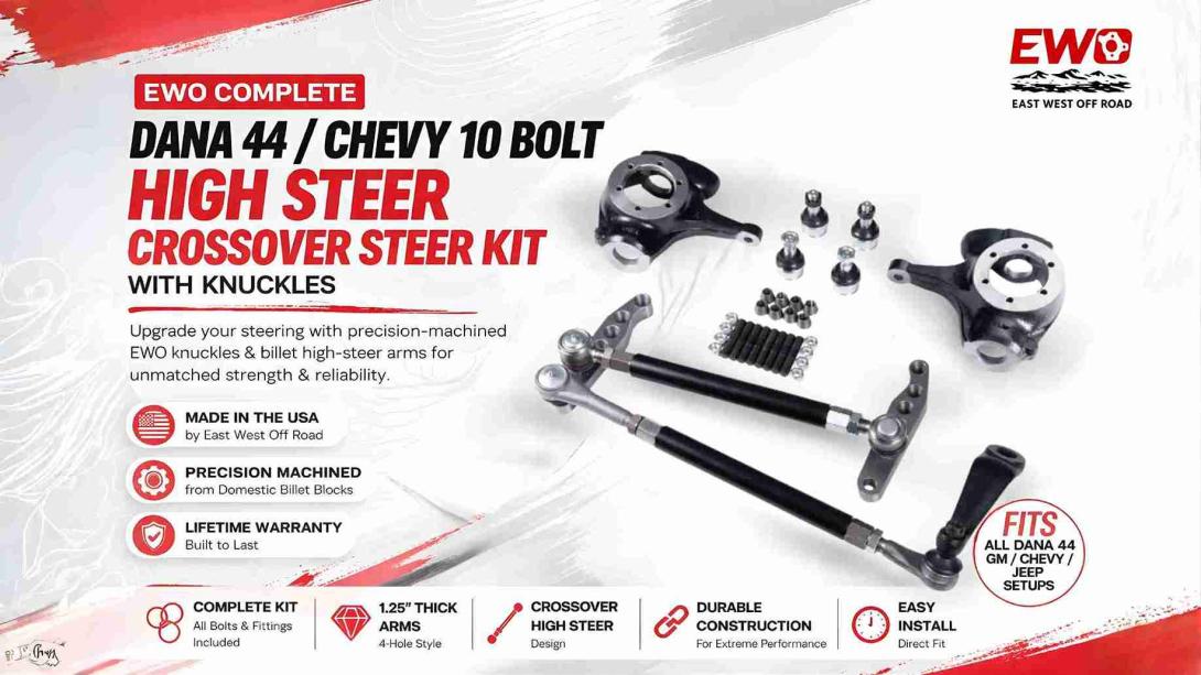
Buy Now: https://www.eastwestoffroad.com/product/ewo-complete-dana-44-chevy-10-b…
ES2026R, ES2027L, ES2234L, and ES2234R steering ends form the articulated connections in the EWO crossover system. The ES2026R and ES2027L are assigned to the drag link, while the ES2234L and ES2234R are assigned to the tie rod. Together with 7/8-18 bungs or tube adapters and left- and right-hand jam nuts, they create adjustable fabricated links. Part numbers do not make installation automatic: each end still needs the correct thread direction, taper, orientation, engagement, operating angle, and clearance.
Which Ends Belong to Which Link?
The confirmed component assignment is straightforward:
Steering link
End at one side
End at the other side
Drag link
ES2026R
ES2027L
Tie rod
ES2234L
ES2234R
The drag link carries input from the pitman arm to the passenger-side high steer arm. The tie rod coordinates the driver- and passenger-side knuckles. Keeping those functions separate helps the fabricator lay out the tubes and identify each tapered connection.
The “L” and “R” designations should be tracked carefully with the actual thread directions and matching bungs. Do not force an end into a mismatched adapter or use part-number suffixes as a substitute for direct inspection.
Why Matched Left- and Right-Hand Threads Help
When a tube assembly uses appropriate opposing thread directions, rotating the tube can change effective link length without removing both ends. That supports tie-rod and drag-link adjustment during alignment and steering setup.
Jam nuts then secure the chosen setting. They need correct thread direction, adequate seating, and practical wrench access. The steering ends must maintain sufficient engagement throughout the usable adjustment range.
Before welding bungs, mark each tube side and lay the entire link on the bench in its intended vehicle orientation. This simple planning step can prevent placing two identical thread directions in one adjustable tube.
Taper Fit Is Separate From Thread Fit
The threaded shank connects an end to the tube assembly. The tapered stud connects the joint to an arm or pitman arm. Both interfaces must be correct, but they are verified differently.
An end can thread into the correct 7/8-18 bung while still having an incompatible taper at the mounting point. Confirm:
● Taper size and angle
● Insertion direction
● Seating depth
● Joint housing clearance
● Stud and fastener condition
● Available angular movement
The EWO steering system with matched ES-series ends provides a known end set and matching linkage materials. Reaming requirements still depend on the actual arms, knuckles, pitman arm, and orientation.
Joint Angle Through Steering and Suspension Travel
Steering ends articulate as the wheels turn and the axle moves. A joint that sits near its limit at ride height can bind at full lock or articulation. Binding can place unintended loads into the end, arm, tube, or pitman arm.
Mock up both links before final fabrication. Check:
● Straight-ahead joint position
● Full left and right steering
● Suspension compression and droop
● Combined steering and articulation
● Boot contact
● Housing contact with arms or wheels
● Thread engagement at adjusted lengths
Do not rely on the fact that the stud can be installed. The joint must move through the vehicle’s usable range without reaching an unsuitable angle.
Inspection and Serviceability
Identified part numbers make future inspection and replacement discussions easier. Owners can record which end belongs at each location, which thread direction it uses, and how the link was adjusted.
Routine checks should look for:
● Joint play
● Torn or displaced boots
● Loose jam nuts
● Damaged threads
● Taper movement
● Contact marks
● Bent linkage
● Weld concerns
Replace or professionally assess questionable parts before continued driving. Do not assume a steering-end warranty or service interval that is not provided in current documentation.
Create a simple location record during installation: pitman-arm end, passenger drag-link end, driver tie-rod end, and passenger tie-rod end. Include each part number and thread direction. That record helps prevent cross-threading during later adjustment and lets a technician order or discuss the correct joint without relying on memory or appearance.
Marking the tubes discreetly by function can provide the same benefit, provided the method does not damage the parts.
For the broader relationship among linkage materials and joints, see the DOM tubing, ball joint, and pitman-arm guide.
Fitment and Installation Considerations
The complete kit is intended for applicable GM, Chevy, and Jeep Dana 44/Chevy 10 Bolt builds and is built around 7/8-inch Chevy 3/4-ton-style ends. Exact vehicle fitment still depends on the axle, arms, knuckles, box, pitman arm, wheels, and suspension.
Installation should include:
1. Assign each end to the correct link and side.
2. Match each threaded shank to the proper 7/8-18 bung or adapter.
3. Verify all four tapered mounting locations.
4. Establish adequate engagement and adjustment range.
5. Measure and cut the DOM tubes on the actual vehicle.
6. Use qualified welding and inspect the links.
7. Cycle steering and suspension before alignment.
8. Secure jam nuts and complete a final safety inspection.
The K10 reaming guide explains why a search for “no reaming” cannot replace this connection-by-connection verification.
Frequently Asked Questions
Are ES2026R and ES2027L tie-rod ends?
In this EWO system, ES2026R and ES2027L are assigned as the drag-link ends. The drag link connects the pitman arm to the passenger-side steering arm. Do not move them to another position based only on appearance. Follow the intended component map and verify threads, tapers, insertion direction, joint range, and clearance.
What are ES2234L and ES2234R used for?
They are the included tie-rod ends in this complete steering system. The tie rod coordinates movement between the driver- and passenger-side knuckles. Each end must match its threaded adapter and the taper at its respective arm or knuckle location. Final orientation and adjustment should be established during professional mockup and alignment.
Can these ends be mixed with different bungs?
Only bungs or adapters with the correct diameter, pitch, thread direction, engagement, material, and fabrication suitability should be used. The package supplies 7/8-18 weld bungs or tube adapters intended for its end set. Mixing unrelated parts requires professional verification and should never be based only on the shank appearing to start into the threads.
Do the four steering ends need grease?
The confirmed source information here does not specify lubrication fittings, grease type, or service procedure for these ends. Follow current product and component instructions rather than inventing a maintenance requirement. Inspect joint condition and boots regularly, and use only the specified service method and lubricant if the manufacturer documentation calls for it.
How much thread engagement should each end have?
No exact engagement value is supplied in the confirmed information, so one should not be invented. The fabricator must design the finished tube lengths to maintain safe engagement throughout the adjustment range, following component and professional guidance. If adequate engagement cannot be achieved with the required link length, the tube or component plan needs correction.
Treat Every End as a Defined Connection
The four part numbers clarify which joints serve the drag link and tie rod, but safe operation comes from correct threads, tapers, angles, and installation. Map each connection before cutting or welding. Builders who want these ends within a coordinated package can review the EWO complete steering system with ES2026 and ES2234 ends.